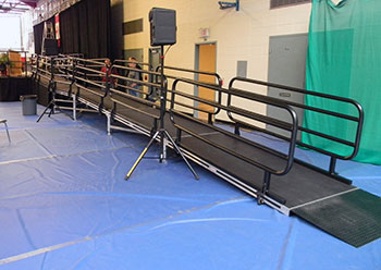
Ultrastage ramps are constructed using standard decks and X-frames, as well as a number of ramp-specific components.
For example, to meet the ADA guideline rise/run ratio of 1:12, a wheelchair ramp to a 26″ stage height would be constructed in the following manner:
We offer a wide range of products and accessories designed to meet the demands of even the most unique and challenging applications. We prioritize meticulous craftsmanship and rigorous quality control throughout the manufacturing process, ensuring every truss meets our high standards. Utilizing durable, high-grade aluminum, we build trusses that are both strong and reliable. Our experienced team’s dedication to precision and attention to detail results in trussing solutions that are built to last. We focus on providing personalized service and tailored solutions, working closely with our clients to understand their specific needs and delivering products that exceed expectations.
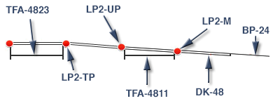
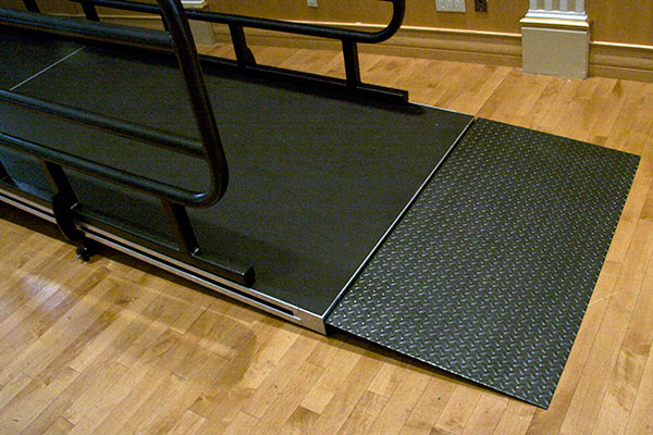
The ramp would start with a BP-24 bumper plate which transitions from floor level to match the surface height of the first 4′ x 8′ deck. Next, a TFA-4811 X-frame is positioned to support the raised end of the first deck.
The telescopic section of the TFA-4811’s lower legs are removed and replaced with angled LP2-M Locator Plates. (LP2-M’s support both the upper end of the first deck and the lower end of the second deck) The first deck is then lowered onto the BP-24’s deck hooks and the LP2-M’s.
With the first deck in position, LP2-UP’s can be placed on the upper telescopic legs of the TFA-4811. (These will support the top end of the second deck and the bottom end of the third deck). After adjusting the telescopic legs to the correct height the second deck is lowered into position on the locator plates. At this point the ramp is 18ft long (including the bumper plate) and 18″ high.
Next, a TFA-4823 X-frame is positioned to support the third inclined deck, and in this example, the stage landing. Once the telescopic legs are adjusted to the correct height LP2-TP’s are installed on the two legs receiving the ramp and LP-1’s, LP-2’s or LP-4’s (depending on the the stage configuration) on the other two legs.
Guard rails would then be attached and deck clamps added to complete the set up. To allow for low ground clearance on the first deck, special ramp guard rails (GR8-L and GR8-R) are required. They can also be used as regular stage railings when required.
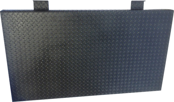
The ramp start with BP-24 secured in place.
Ramp Starter Plate. Model: BP-24 showing its deck locking “claws”. Powder coated diamond-plate steel construction
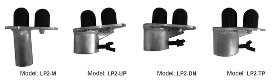
There are FOUR specialized models of locator plates used in UltraStage Ramp construction. In straight ramp construction only 2 x LP2-M and 2 x LP2-TP will be used, while quantities of LP2-UP and LP2-DN will depend on the length of the ramp.